


In order to remotely control the Arduino by connecting to the WiFi module ESP01 in the Android application ADUCON / ADUPAD, the WiFi module ESP01 and Arduino must be well wired in hardware. In addition, the serial communication baud rate for data transmission of ESP01 must be set to 9600 so that it can be used on the Arduino board.
Preparations
- Connection between Arduino Uno board and ESP01

TX -> Arduino RX
RX -> Arduino TX
VCC -> Arduino 3.3V
CH_PD -> Arduino 3.3V
GND -> Arduino GND

- Set the serial communication baud rate of module ESP01 to 9600
The default baud rate for ESP01 is 115200. Arduino's softwareSerial can also be used as a baud rate 115200. However, in this case, errors sometimes occur during data transmission. The baud rate at which softwareSerial operates stably is 9600. Therefore, it is necessary to change the baud rate of ESP01 to 9600 so that it can be connected to Arduino and used normally.
- How to check baud rate of the module
1. Module and Arduino must be well wired in hardware.
2. Upload the basic Sketch which is coded baud rate 115200 of Serial.
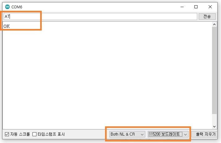
3. Set option to "Both NL & CR" for Serial Monitor of Arduino IDE.
4. Set baud rate to "115200" at Serial Monitor of Arduino IDE.
6. Input "AT" at text window and if get "OK" as a response, the baud rate of the module is 115200.
7. If not, try to change baud rate to 9600 or another value in the sketch and upload.
8. Set baud rate to "9600" or another value at Serial Monitor of Arduino IDE.
9. Input "AT" at text window and if get "OK", the baud rate of the module is 9600. if not repeat no.7 ~ 9.
#include <SoftwareSerial.h>
SoftwareSerial esp01(2, 3); // SoftwareSerial NAME(RX, TX);

void setup() {
  Serial.begin(115200);  // Serial Monitor and baud rate
  esp01.begin(115200);   // ESP01 serial and baud rate
}

void loop() {
  if (esp01.available()) {
    Serial.write(esp01.read()); //Output the contents of the ESP01 to the serial monitor
  }
  if (Serial. available()) {
    esp01.write(Serial.read()); //Write the contents of the serial monitor to the ESP01
  }
}
If the baud rate is not set to 9600, please set it by referring to the below.
Set the transmission option of the serial monitor to Both NL & CR and the baud rate to 115200. Then, type "AT" into the Arduino serial monitor input window and hit enter. If OK is displayed on the serial monitor as a response, you can confirm that the Arduino and ESP01 are well connected and are operating normally. Copy and paste the AT command "AT+UART_DEF=9600,8,1,0,0" to change the baud rate and hit enter. If you receive an OK response, the baud rate of ESP-01 has been changed to 9600.


Precautions when using the WiFi module ESP01
1. When transmitting data, AT command must be executed through serial communication every time.
2. When Arduino is operating as a server and the use of multi-connection is forced as a connection option, if the id used for receiving is in use or not terminated, the next id will receive additional requests.
3. If an additional request comes while all 5 connection ids are connected, all of them are closed. In this state, it must be reset to be usable again.
4. In order to prevent the third case, when data reception is completed, the id connection must be disconnected and the ID state must be put on standby.
5. In case of receiving continuous data, the data is received while the id is changed. At that time, the time order of the received data may be changed.
6. For the reason of No. 1, it takes more than 1 second to respond to data reception. Therefore, it is difficult to respond to rapidly received data, so it is recommended to use the SeekBar (slide bar) mode as "Passive Slide Mode".
*** If you want to receive continuous values using "Active Slide Mode", you must code not to respond to reception so that all 5 connection ids are not filled. At the same time, the data transmission interval must be properly set in the application so that values can be received at appropriate time intervals.
Key code for remote control
- Set Software serial to communicate with ESP01.
#include <SoftwareSerial.h>
#define rxPin 3
#define txPin 2
SoftwareSerial esp01(txPin, rxPin); // SoftwareSerial NAME(RX, TX);
- ACCESS POINT name and password setting for ESP-01
const char ssidAP[] = "ESP01";   // your network SSID (name)
const char passAP[] = "12345678"; //"1234test";         // your network password
- If you want to use the internal network through a router connection, set the name and password of the router that ESP01 needs to connect to.
const char ssid[] = "skynet";    // "SK_WiFiGIGA40F7" your network SSID (name)
const char pass[] = "skynet00";  // "1712037218" your network password
- Function that executes AT command for ESP01 setup
String sendData(String order) {
  String command = F("AT+");
  command += order;
  command += F("\r\n");
  esp01.print(command); // send the command to the esp01
  long int time = millis();
  String response = "";
  while( (time+20000) > millis()) {
    while(esp01.available()) {  // if The esp has data
      char c = esp01.read();    // read the next character.
      response+=c;
    }
    if (response.indexOf(F("OK")) != -1) { retry = 0; Serial.println(F("OK")); break; }
    else if (response.indexOf(F("FAIL")) != -1 || response.indexOf(F("ERROR")) != -1) {
      if (response.indexOf(F("FAIL")) != -1) retry++;
      else if (response.indexOf(F("ERROR")) != -1) { Serial.println(F("ERROR")); break; }
      Serial.print(command); Serial.println(F("Failed")); break;
    }
  }
  return response;
}
- Function that executes AT Command for data transmission and terminates the connection ID
uint8_t connectionId = 48; // connection id

void http_response() {
  String cip = F("AT+CIPSEND=");
  cip += connectionId-48;
  cip += ',';
  cip += Data.length()+19;
  cip += F("\r\n");
  esp01.print(cip);
  unsigned long int time = millis();
  while (time+2000 > millis()) {
    cip = esp01.readStringUntil('\n');
    if (cip.indexOf(F("OK")) != -1) { break; }
  }
  esp01.print(F("HTTP/1.1 200 OK\r\n\r\n")); // +19
  esp01.print(Data);
  time = millis();
  while (time+2000 > millis()) {
    cip = esp01.readStringUntil('\n');
    if (cip.indexOf(F("OK")) != -1) { break; }
  }
  Data = "";
  String command = F("AT+CIPCLOSE=");
  command += String(connectionId-48);
  command += F("\r\n");
  esp01.print(command);
}
- setup() function
void setup() {
  pinMode(ledPin, OUTPUT);   // Set the default LED (13) of the Arduino Uno as an output
  digitalWrite(ledPin, LOW); // set the initial state of the primary LED (13) to off
  Serial.begin(9600); // Set the baud rate for communication with the serial monitor of the Arduino IED to 9600
  esp01.begin(9600);  // Set baud rate for communication with ESP01 to 9600
  sendData(F("RST")); // AT Command: ESP01 module reset
  unsigned long int time = millis();
  String temp = "";
  while (time+20000 > millis()) { // Wait until ESP01 is reset
    temp = esp01. readStringUntil('\n');
    if (temp. indexOf(F("ready")) != -1) { Serial. println(F("Set")); break; }
  }
  if (wifiRouter) sendData(F("CWMODE=3")); // AT Command: Access point and router connection setup (AP+STA)
  else sendData(F("CWMODE=2"));            // AT Command: set access point only
  if (wifiRouter) sendData(F("CWDHCP=1,1")); // Set the use of DHCP when connecting to a router
  sendData(addID(F("CWSAP="),ssidAP,passAP)+','+String(10)+','+String(3)); // AT Command: AP execution
  sendData(F("CIPMUX=1"));       // AT Command: Multi Connection Settings
  sendData(F("CIPSERVER=1,80")); // AT Command: set server port number 80
  if (wifiRouter) { // In case of router connection
    retry = 1;
    while(retry) {  // If the router fails to connect, repeat the connection
      sendData(addID(F("CWJAP="),ssid,pass)); // AT Command: Launch router connection
      if (retry > 1) { Serial. print(F("Retrying to connect: ")); Serial. println(retry-1); }
      if (retry > 4) { Serial. println(F("connection failed")); retry = 0; }
    }
  }
  ipCheck(sendData(F("CIFSR"))); // AT Command: Check the current AP/IP address and store it in variables ap, ip
}
- loop() function
bool gotData = false;

void loop() {
  if (esp01.available()) { // when incomming data from ESP01
    String temp = esp01.readStringUntil('\n'); // read string until character '\n'
    Serial.println(temp); //Output the contents of the ESP01 to the serial monitor
    if (temp.startsWith("+IPD")) {    // if the string start with "+IPD"
      gotData = true;                 // the flag for response of HTTP
      temp.remove(0,5);               // remove "+IPD,"
      connectionId = temp.charAt(0);  // get connection ID from first character of temp
    }
  } else {
    if (gotData) {                    // if response of HTTP
      Data = "Hello World ";
      Data += random(100,200);        // the message for sending
      Serial.println(Data);           // output Message to the serial monitor
      http_response();                // response of HTTP
      gotData = false;                // initialize the flag
    }
  }
}
ARDUINO_ESP01_BASIC.zip
- Output of Serial Monitor after upload scketch "ARDUINO_ESP01_BASIC.ino"

Connecting directly to the ESP01 and then connecting the access point
- Connect to ESP01 on the WiFi Setting of a mobile phone.

- Input the Password for the ACCESS POINT of ESP01.

- Select "Keep WiFi on" if the message output below.

- Input the address "192.168.4.1/hi" on web browser.


Connecting to the assigned IP while ESP01 is connected to the router
- Input the assigned IP address "192.168.1.7/hi" on web browser of PC connected to network of "skynet".


[Arduino/ADUCON] - Arduino WiFi remote control with ADUCON and ESP-01
[Arduino/ADUPAD] - Arduino WiFi remote control with ADUPAD and ESP-01
[Arduino/ADUCON] - ADUCON - Arduino wireless remote control application
[Arduino/ADUPAD] - ADUPAD - Arduino wireless remote control PAD application
https://play.google.com/store/apps/details?id=com.tistory.postpop.hmi
ADUCON - Google Play 앱
무선(WiFi/Bluetooth/BLE)을 통한 Arduino 원격 제어 앱
play.google.com
https://play.google.com/store/apps/details?id=io.kodular.skyship72.pad01
ADUPAD - Google Play 앱
무선(WiFi/Bluetooth/BLE)을 통한 Arduino 원격 제어 PAD
play.google.com
'Arduino' 카테고리의 다른 글
| ESP32 CAM 화질 테스트 및 온보드 LED 플래시 라이트 제어하기 (0) | 2023.01.24 |
|---|---|
| ESP32/NodeMcu Basic code for WiFi remote contol (0) | 2022.11.29 |
| Arduino Basic code for BLE remote contol with BT05 (0) | 2022.11.25 |
| Arduino Basic code for bluetooth remote contol with HC-06 (0) | 2022.11.23 |
| 아두이노 - 와이파이, ESP01 wifi 모듈 무선 원격제어 그리고 시리얼 통신 - 6편 (10) | 2022.06.08 |
| arduino - Simple Melody 이용 피에조 부저 멜로디 코딩하기, Esp01, EEPROM (0) | 2020.09.19 |
| ESP8266 / ESP32 - SPIFFS 파일시스템 라이브러리 예제 및 사용방법 (4) | 2020.03.22 |
| 아두이노 - ESP01 와이파이 매니저, soft AP이용 공유기 연결용 아이디와 비밀번호 설정하기, wifimanager (0) | 2019.11.24 |